WAGO CC100 Controller#
Required information for the WAGO PLC Program#
In order for Octave to program the PLC according to your specific setup, please provide us with the following documents:
- Single Line Diagram (SLD)
- Grid study (ORES / Fluvius / Resa)
Product overview#
The WAGO CC100 (751-9402) is a compact PLC with:
- 8x DI, 8x DIO
- 2x AI, 2x AIO
- 2x RTD inputs
- 2x RS-485
- 2x Ethernet
- microSD slot
- USB-C service interface
Below is a a visual reference of the WAGO CC100 controller with its main connectors and interfaces labeled.
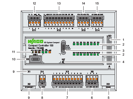
Legend:
- Memory Card Slot
- LEDs Status DI/DIO
- Mode Selector Switch
- Reset Button
- Communication Interface X8
- Analog Inputs/Outputs - X6
- Digital Inputs/Outputs - X5
- Supply Voltage - X4
- ETHERNET Interfaces - X1, X2
- USB-C Service Interface - X3
- System LEDs
- Communication Interface X11
- Digital Inputs - X12
- RTD Inputs - X13
- Analog Inputs - X14
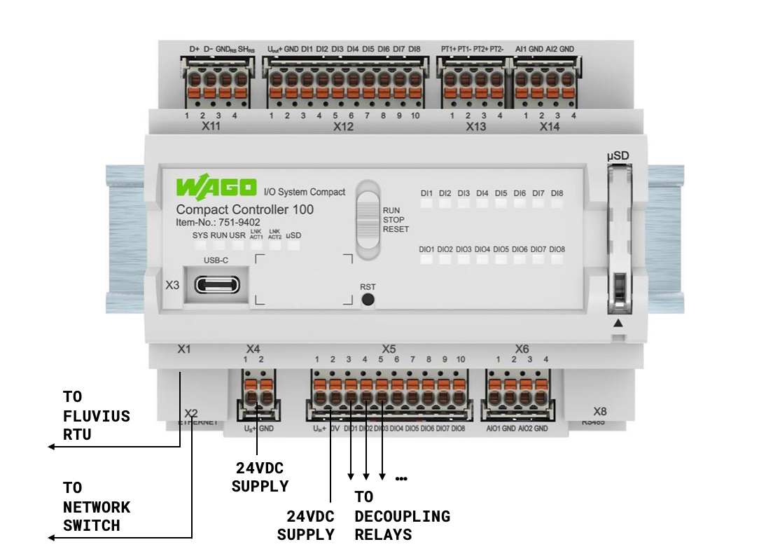
Main connectors (reference)#
- X4: System supply (24 VDC)
- X5: Field I/O supply (24 VDC) + DIO1…DIO8 (depending on wiring)
- X6: Analog I/O (AIO)
- X12: Digital inputs (DI)
- X13: RTD inputs
- X14: Analog inputs (AI)
- X1 / X2: Ethernet interfaces
- X3: USB-C service interface
- X8 / X11: RS-485 interfaces
Mechanical installation#
Mounting on DIN rail#
- Tilt the device slightly.
- Hook the top edge onto the DIN rail.
- Press down until it audibly clicks.
- Gently shake to verify secure locking.
- Install end-stops on both sides.
Electrical connections#
All connectors are included but not pre-installed.
Power supply#
Two power inputs must be wired:
1) System supply — X4
- Pin 1: US+ (24 VDC)
- Pin 2: GND
2) Field I/O supply — X5
- Pin 1: Uin+ (24 VDC)
- Pin 2: 0V
Important: Power on X5 before or at the same time as X4
Digital inputs — X12 (DI1…DI8)#
10-pole connector:
- Pin 1: Uout+ (sensor supply)
- Pin 2: GND
- Pins 3–10: DI1…DI8 (24 VDC, type 3)
Input LED ON = high (24 V).
Digital inputs/outputs — X5 (DIO1…DIO8)#
- DIO1–DIO8 support both input and output (0.5 A max).
- Pins 3–10: DIO1…DIO8
- Outputs are high-side switching.
Relay contacts
These DIOs can be wired as dry contacts to control the decoupling relays (used on Fluvius TC5 projects).
Analog inputs — X14 (AI1, AI2)#
Supported ranges:
- 0–10 V, ±10 V
- 0–20 mA, 4–20 mA, 3.6–21 mA
Pinout:
- Pin 1: AI1
- Pin 2: GND
- Pin 3: AI2
- Pin 4: GND
Analog I/O — X6 (AIO1, AIO2)#
- Same input ranges as above
- Plus analog output ranges: 0–10 V, ±10/12 V, 0–22 mA
Pinout
- Pin 1: AIO1
- Pin 2: GND
- Pin 3: AIO2
- Pin 4: GND
RTD inputs — X13 (PT1, PT2)#
Supports Pt100/500/1000, Ni100/1000, potentiometers.
Pinout:
- Pin 1: PT1+
- Pin 2: PT1–
- Pin 3: PT2+
- Pin 4: PT2–
Ethernet — X1 / X2#
- RJ45
- Can be configured as switch mode (one IP) or separate interfaces (two IPs)
Connection to the RTU
The X1 Port is reserved to connect to the DSO RTU (for Fluvius TC5 projects)
Connection to the Site Network
The X2 Port is used to connect to the Site Network. It’s usually set to DHCP.
USB-C service port — X3#
Used for commissioning with WAGO Ethernet Settings.
- Device appears at 192.168.42.42 over USB
RS-485 interfaces — X8, X11#
First startup / commissioning#
Power-up#
- Turn on 24 VDC supply.
- SYS LED blinks → device booting.
- SYS steady green → system ready.
- RUN LED green → PLC program running (if present)
Network configuration#
Network settings
Leave the network configuration at its defaults. Octave Operators will adjust it when programming the PLC.
The CC100 PLC supports several IP configuration methods. The selected method is evaluated during startup in the order defined in the manual.
Default addresses#
- USB connection: 192.168.42.42
- Ethernet X1/X2: DHCP by default
LED quick diagnostics#
- SYS: Green = OK, Orange = booting, Flash orange = temp IP
- RUN: Green = program running, Flashing = no app, Red = STOP
- DI/DIO: Green = channel high
- LNK/ACT: Green = link, Flash = traffic
- µSD: Orange = access
Reference#
Quick start: Quickstart cc100.pdf
Datasheet: Compact Controller 100; 8DI 4DO 2AI 2AO 2NI1K/PT1K 1RS485; 2 x ETHERNET; SD
Product Manual: WAGO | 6835960