WAGO Remote I/O#
Hardware#
Bill of materials#
The following modules need to be assembled in this order:
-
750-362 — Modbus TCP head station
-
750-602 — Power supply for the next I/O modules (24 VDC)
-
750-450 — 4× Analog Input (4AI)
-
750-550 — 2× Analog Output (2AO)
-
750-430 or 750-1415 — 8× Digital Input (8DI)
-
750-530 or 750-1515 — 8× Digital Output (8DO)
-
750-600 — End module
750-362 — Modbus TCP Head Station#
This section is based on the WAGO 750-362 short guide below
Product overview#
The WAGO 750-362 is a Modbus TCP/UDP fieldbus coupler for the WAGO I/O System 750/753.
Key features
- Communication protocol: Modbus TCP/UDP
- 2× RJ45 Ethernet ports with integrated switch
- Automatic detection of up to 64 I/O modules
- Integrated web server for configuration and diagnostics
- IP configuration via DIP switch, DHCP, BootP or static IP
- Status indication via front LEDs
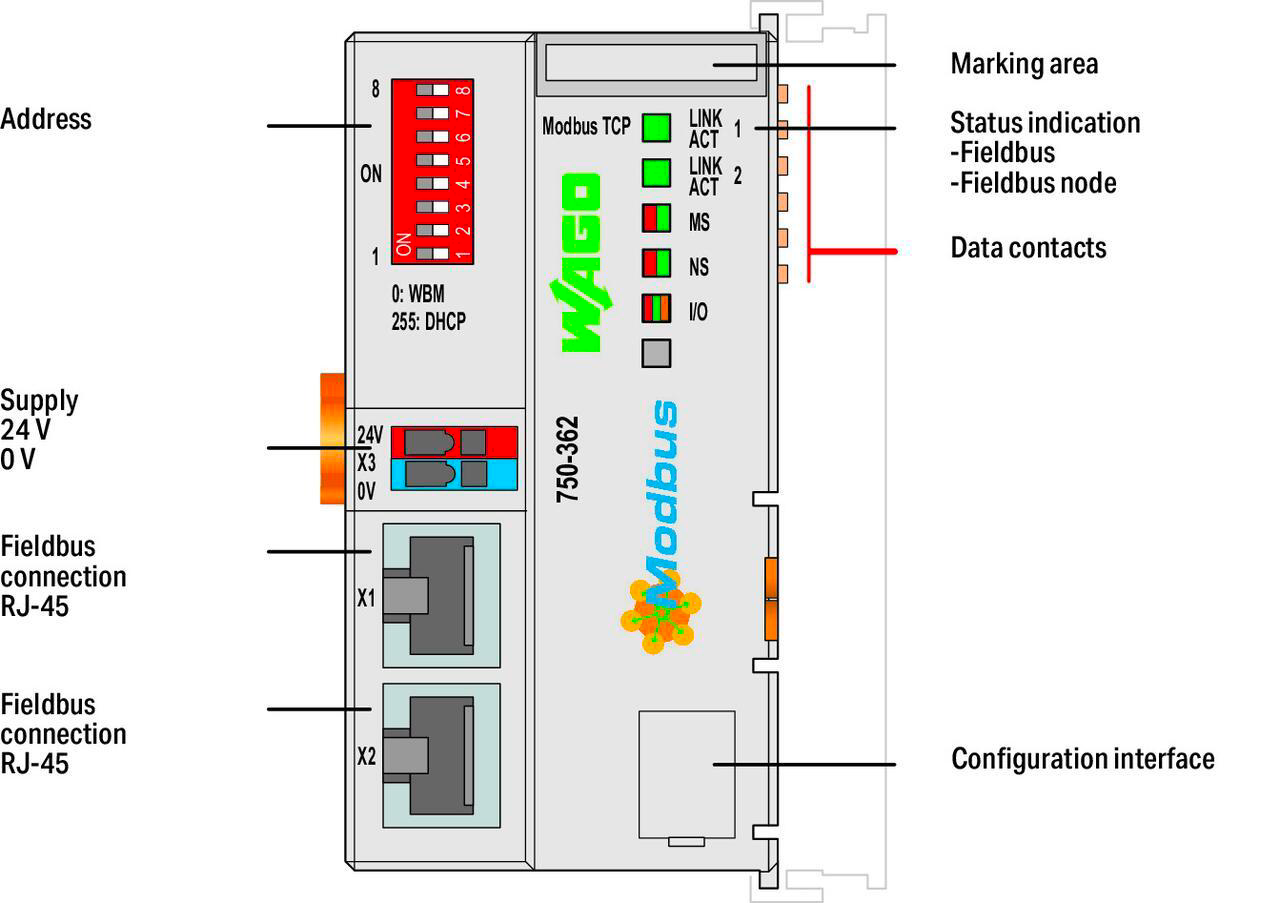
Main connectors (reference)#
- X3: System supply (24 VDC, 0 V)
- X1 / X2: Ethernet interfaces (RJ45, integrated switch)
Mechanical installation#
Mounting on DIN rail#
- Snap the coupler onto a DIN rail.
- The coupler must be installed as the first module on the left of the I/O station.
- Attach I/O modules to the right until the internal data bus is continuous.
- Ensure the locking mechanism is fully engaged.
Electrical connections#
System supply — X3#
- Nominal voltage: 24 VDC (–25 % … +30 %)
- Pin 1: 24 V
- Pin 2: 0 V
Field supply#
- The field supply for the I/O modules is not provided by the coupler.
- Use dedicated power supply modules of the 750 system (e.g. 750-602).
- Field power is routed via the integrated power jumper contacts to adjacent I/O modules.
Ethernet — X1 / X2#
- 2× RJ45 ports with integrated switch
- Pin 1: TD+
- Pin 2: TD–
- Pin 3: RD+
- Pin 6: RD–
- Pins 4, 5, 7, 8: free
First startup / commissioning#
- Power up the 24 VDC system supply.
- The coupler performs an internal self-test.
- All connected I/O modules are scanned and registered automatically.
- The internal I/O bus status is indicated by the I/O LED.
- Once startup completes successfully, the coupler is ready for Modbus communication.
If an error occurs during startup, it is signalled by red or orange LED states; the integrated web server provides detailed diagnostic information.
Network configuration#
Network settings
Leave the network configuration at its defaults. Octave Operators will adjust it when programming the PLC.
The 750-362 supports several IP configuration methods. Please refer to the manual or reach out to Octave for more information.
Default addresses#
- Delivery state: DHCP active (dynamic IP assignment)
- Static base IP address (when DHCP is disabled): 192.168.1.0
- Default subnet mask: 255.255.255.0
- Default gateway: 0.0.0.0
LED quick diagnostics#
- LNK ACT 1 (green): link to the physical network on port 1
- LNK ACT 2 (green): link to the physical network on port 2
- MS (red / green): module status of the node
- NS (red / green): network status
- I/O (red / green / orange): node operation; signals faults via blink codes